Emissions modeling requires information about the subsequent air quality modeling that will be done. For example, to produce appropriate model-ready files using SMOKE, you must know which AQM will be used, the model grid and map projection, the episode dates, and the chemical mechanism to be used. In this manual, we refer to these settings collectively as “modeling parameters”. In this section, we provide information on what these modeling parameters are and SMOKE’s capabilities to support them.
SMOKE reads in the modeling parameters from both script settings (environment variables) and input files. In the subsections below, we provide the relevant settings and files that control the modeling parameters. More information about how to configure your scripts and files to change these parameters can be found in Section 4.4, “How to use SMOKE”; how the settings affect the programs is described in Chapter 5, SMOKE Utility Tools and Chapter 6, SMOKE Core Programs.
A map projection is the mathematical representation of the spherical surface of the earth on a 2-D plane. SMOKE supports Lambert conformal, lat-lon, UTM, and polar stereographic map projections. There are many different settings that you may use to define your Lambert conformal, UTM, and polar stereographic projections, to make these projections match the one being used by your meteorology model and AQM. (Lat-lon is a fixed projection and cannot be changed.)
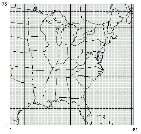
A model grid is a two-dimensional region overlaid on a map projection. It is defined by the starting x-y coordinates, the number of grid cells in each direction, and the physical size of the grid cells. Figure 2.2, “Example model grid” shows an example of a model grid that includes most of the eastern U.S. This example has 81 grid cells in the x-direction, 75 grid cells in the y-direction, and each grid cell is 36 by 36 kilometers. Each set of 10 cells by 10 cells (counting from the starting coordinates) is enclosed in black grid lines.
The model grid is set in SMOKE using the IOAPI_GRIDNAME_1 setting to select a grid and map projection from among those defined in the GRIDDESC input file. The name of the grid set with the IOAPI_GRIDNAME_1 setting must match a grid name in the GRIDDESC file to allow SMOKE to obtain the grid and map projection parameters from the GRIDDESC file.