There are eight data-structure types and three basic data-types for variables in files presently supported by the I/O API. The I/O API was designed so that this list of file types might be extended with relatively little effort. The types are associated with file type "magic number" parameter values which are defined inINCLUDE-filePARMS3.EXT. The current set of structure-ypes, together with the names of the magic number parameters, is given by the list below. Note that declarations are given in terms ofREAL*4andREAL*8; this will protect you if you do things like using precision-doubling software or f90 -r8 ... compiler flags to force double precision calculations in your code and linking the wrong version of the low-level XDR data representation library by accident. (If you don't do these things, usingREALin these declarations is quite all right.)
The list of file types, together with the magic numbers for each, is:The file's data structure type value is stored in the
- CUSTOM3: custom ,
- DCTNRY3: dictionary ,
- GRDDED3: gridded ,
- BNDARY3: boundary ,
- IDDATA3: ID-referenced ,
- PROFIL3: vertical profile ,
- GRNEST3: nested grid, and
- SMATRX3: sparse matrix,
- KFEVNT3: cloud-event
- TSRIES3: (hydrology) time series
- PTRFLY3: pointer-flyer
FTYPE3Dvariable of the file header and the file description data structures inFDESC3.EXT. Note that all the variables in a file have the same structural data type, the same dimensionality and layer structure, and the same time step structure, but possibly different basic types. The vast majority of air quality modeling files are of the gridded or boundary structural types of basic typeREAL, which need only ordinary arrays to write from or read into. For the other types, you will have to set upCOMMONs as described below, to match the data structure for the variables in the file.
Independent of data structure-types, there are three categories of basic or underlying types which each variable in the data records may have. Note that each variable has a basic type of its own; it is quite legitimate to have a gridded file with 5 gridded integer variables, 3 gridded real variables, and 7 gridded double-precision variables. Basic data type for variables is stored in theVTYPE3D(:)array of the file header and the file description data structures inFDESC3.EXT. The list of data types, together with the "magic numbers" (chosen to be consistent with existing netCDF magic numbers) for each (defined consistently with netCDF usage, in INCLUDE-file PARMS3.EXT ) is the following:Additionally, I/O API
- M3INT:
INTEGER(4-byte integer, = netCDF nf_int)- M3REAL:
REAL(single-precision, = netCDF nf_float)- M3DBLE:
DOUBLE PRECISION(at least 8-byte, = netCDF nf_double)MODULE MODNCFIOandMODULE MODMPASFIOsupport high-level data access to variables in their respective file-types, which may also include variables of the following four types:
- M3BYTE:
INTEGER*1(1-byte integer, = netCDF nf_byte)- M3CHAR:
CHARACTER(= netCDF nf_char)- M3INT2:
REAL(single-precision, = netCDF nf_short = nf_int2)- M3INT8:
INTEGER*8(at least 8-byte, = netCDF nf_int64)Currently, only real variables are supported by routines
INTERP3()andDDTVAR3(), and analysis program M3STAT (before I/O API-3.2), and M3DIFF; only integer and real variables are supported for buffered virtual files.
Independent of data structure-types, there are also three categories of time structure for the data records, discriminated on the basis of theTSTEP3Dattribute, and further specified by the starting date and timeSDATE3DandSTIME3Dattributes in the file header and FDESC data structures. Time step and starting date and time are stored according to Models-3 time conventions . Internally, the I/O API maintains the value of MXREC3D, the maximum time step record number, which describes "how long" the file is. The categories of time step structure are:
- Time-independent.
TSTEP3D = 0, andSDATE3DandSTIME3Dare ignored.
MXREC3Dis either 0 (for an empty file) or 1.- Time-stepped.
TSTEP3D > 0, andSDATE3D:STIME3Drepresent the starting date&time for the file's time step sequence.
There are at mostMXREC3Dtime steps in that sequence.- Circular-buffer.
TSTEP3D < 0is the negative of the actual time step; the file keeps only two time steps of data, the "even" part and the "odd" part.SDATE3D:STIME3Drepresent the starting date&time for the file's time step sequence.
There are at mostMXREC3Dtime steps in that sequence.Each of these data types supports multiple time steps of multiple layers of multiple user-defined variables , as indicated below (a time step of a variable being all of the data values associated with the date and time of that time step.)
In some cases, there are additional system-defined variables which are part of the data structure (e.g., theNUMIDSin the ID-referenced-data data structure, below). Where such system-defined variables are present, the operationsREAD3()andWRITE3()act on entire time steps -- i.e., of all variables -- at once; otherwise, they can be used to store or retrieve time steps of individual variables one at a time. There are moderate performance advantages to writing the variables for a time step in the same order that they appear in the file description, and for writing the time steps in consecutive order; however, this is not required by the I/O API (which permits any access order to the data, for both read and write operations).
custom data--this is just a user-dimensioned array of REAL, INTEGER, or DOUBLE PRECISION that the system reads and writes reliably; it's up to you to interpret its structure for yourself. (This type was included on the "I probably haven't thought of everything" principle.) A typical argument declaration for a set of variables to be used with a CUSTOM file would look like the following, where the dimensioning constantSIZEmaps into theNCOLS3Dfile description parameter;NROWS3DandNTHIK3Dare ignored):...(SIZE is a fixed, user-defined dimension:) REAL*4 ARRAY( SIZE, NLAYS, NVARS )
dictionary--the reusable parts of a file description; this data type is used to store and retrieve the following parts of an FDESC3.EXT file description:FTYPE3D, TSTEP3D, NCOLS3D, NROWS3D, NLAYS3D, NVARS3D, NTHIK3D, GDTYP3D, P_ALP3D, P_BET3D, P_GAM3D, XORIG3D, YORIG3D, XCELL3D, YCELL3D, GDNAM3D, XCENT3D, YCENT3D, VNAME3D, UNITS3D, VDESC3DNote that all of these dimensioning and descriptive attributes are, of course, themselves not applicable to the DCTNRY3 file, and that the data structures for storage and retrieval are already defined for you in FDESC3.EXT . Dictionary files can be used to make much easier the process of file creation within a particular model. To do this, you would begin by standardizing on names for file structure templates, and then build a dictionary file which contains these templates. A modeler needing to create or open a file with template name "FOO" and logical name "MY_FOO" using the dictionary with logical name "D" would then do the following (using the dictionary file, routines READ3() to get the FDESC3.EXT file description and OPEN3() to create or open the file using it):... C........ Assume that dictionary file D has been opened. C........ Use READ3() on this dictionary file to put the C........ standard parts of a file description into C........ the FDESC3 data structures: IF ( .NOT. READ3( 'D', 'FOO', 0, 0, 0, 0 ) ) THEN CALL M3ERR( 'my routine', 0, 0, & 'Could not read file template FOO from dictionary D', & .TRUE. ) END IF C........ Now put the timestep, starting date, and starting time C........into the file description SDATE3D = JDATE STIME3D = JTIME TSTEP3D = TSTEP C........ Call OPEN3 to open FOO (in this case as an UNKNOWN -- C........ create if necessary; otherwise perform consistency check): IF ( .NOT. OPEN3( 'MY_FOO', FSUNKN3, 'my routine' ) ) THEN CALL M3EXIT( 'my routine', JDATE, JTIME, & 'Could not open/create file MY_FOO', 2 ) END IF ...Dictionary files support model management policies having standardized file templates, but do not mandate them (since one can fill in an entire file description in-line before calling OPEN3() to create non-standard files). This gives opportunities both for rigor and accountability and for flexibility. An interesting application of the flexibility and power thus afforded is that of multiple-grid situations such as you find with two-way nesting, where it is perfectly reasonable to have one dictionary per grid (say "D_GRID1" , "D_GRID2" , ..., with all the dictionaries sharing a common set of names for the templates they contain. Programs can then fetch file descriptions (say for the grid-n template "FOO") as"READ3( 'D_GRIDn', 'FOO', ... "
gridded data, dimensioned as in:REAL*4 ARRAY( NCOLS, NROWS, NLAYS, NVARS )Note thatNTHIK3Dis ignored.
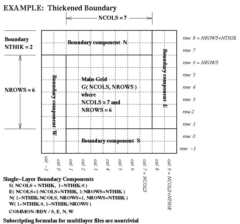
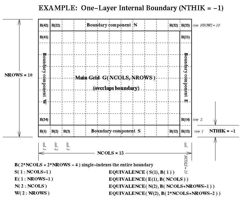
grid-boundary data for an external perimeter to a grid. This perimeter isNTHIKcells wide (where you may use a negativeNTHIKto indicate an internal perimeter such as is used by ROM and RADM). The boundary array is dimensioned as follows in terms of the dimensions for the array it surrounds:...(SIZE = ABS( NTHIK )*(2*NCOLS + 2*NROWS +4*NTHIK) REAL*4 ARRAY( SIZE, NLAYS, NVARS )There are accompanying diagrams illustrating the data layout for various cases of NTHIK:
- the general thickened-boundary case, NTHIK > 1, available as Postscript, as X11 Bitmap, as JPEG, or as GIF;
- the simple case, NTHIK = 1, available as Postscript , as X11 Bitmap, as JPEG , or as GIF;
- the internal-boundary case, NTHIK = -1 (< 0), available as Postscript, as X11 Bitmap, as JPEG, or as GIF;
ID-referenced data, used to store lists of data like surface meteorology observations, pollution-monitor observations, or county-averaged concentrations. (ROM people note: this is a generalization of ROM Type 2 and 3 files, except that if you want the positions and elevations, you have to list them as variables yourself.) An example of observational data with up to 100 sites, each measuring temperature, pressure, and relative humidity is the following:... INTEGER*4 MAXID ! max permitted # of sites PARAMETER ( MAXID = 100 ) ... INTEGER*4 NUMIDS ! number of actual sites INTEGER*4 IDLIST( MAXID ) ! list of site ID's REAL*4 XLON ( MAXID ) ! first variable in file REAL*4 YLAT ( MAXID ) ! second variable REAL*4 TK ( MAXID ) ! third variable REAL*4 PRES ( MAXID ) ! fourth variable REAL*4 RH ( MAXID ) ! fifth (last) variable COMMON /FOO/ NUMIDS, IDLIST, XLON, YLAT, TK, PRES, RHThe dimensionMAXIDmaps into theNROWS3Ddimension in the file description data structureFDESC3.EXT, for use byOPEN3()orDESC3().NCOLS3DandNTHIK3Dare ignored. To read or write this data, put the first element,NUMIDS,of this common in the "array" argument spot ofREAD3()orWRITE3():IF ( .NOT. WRITE3( 'myfile', 'ALL', JDATE, JTIME, NUMIDS ) ) THEN ...(some kind of error happened--deal with it here) END IF
vertical profile data (rawindsonde data), which has a sufficiently different structure from other observational data (having possibly a site-dependent number of levels at each site) that it deserves a special data type of its own. (This is a generalization of ROM Type 1 files.) An example of the sort of data structure needed for a rawinsonde file with variables ELEV, TA, and QV given at up to 50 stations, each of which may have up to 100 observation levels, is given by the following. Note that in this case, ELEV = "height of the level above ground" is user-specified as one of the variables.... INTEGER MXIDP ! max # of sites INTEGER MXLVL ! max # of levels PARAMETER ( MAXID = 50, MXLVL = 100 ) ... INTEGER NPROF ! # of actual sites INTEGER PLIST( MXIDP ) ! list of site ID's INTEGER NLVLS( MXIDP ) ! # of actual levels at site REAL*8 X ( MXIDP ) ! array of site X-locations REAL*8 Y ( MXIDP ) ! array of site Y-locations REAL*8 Z ( MXIDP ) ! array of site Z-locations REAL ELEV ( MXLVL, MXIDP ) ! height of lvl a.g.l. REAL TA ( MXLVL, MXIDP ) ! variable "TA" REAL QV ( MXLVL, MXIDP ) ! variable "QV" COMMON /BAR/ NPROF, PLIST, NLVLS, X, Y, Z, ELEV, TA, QV ...The site dimensionMXIDPmaps into theNROWS3Ddimension , and the levels dimensionMXLVLmaps into theNCOLS3Ddimension in the file description FDESC3.EXT data structures.NTHIK3Dis ignored. To read or write this data, put the first element,NPROF,of the commonBARin the "array" argument spot ofREAD3()orWRITE3():IF ( .NOT. WRITE3( 'myfile', 'ALL', JDATE, JTIME, NPROF ) ) THEN ...(some kind of error happened--deal with it here) END IF
Coded but never used: nested-grid data should be considered as a preliminary and experimental implementation for storing multiple grids, which need not in fact have any particular relationship with each other beyond using the same coordinate system. An example of the sort of data structure needed for a nest of grids for variables NO2 and O3 is the following:... INTEGER*4 MXNEST ! max # of nests INTEGER*4 MXGRID ! max # of cells (total, all grids) INTEGER*4 MXLAYS ! max # of levels PARAMETER ( MXNEST = 10, MXGRID = 10000, MXLAYS = 25 ) ... INTEGER*4 NNEST ! # of actual nests INTEGER*4 NLIST( MXNEST ) ! list of nest ID's INTEGER*4 NCOLS( MXNEST ) ! # of actual cols of nest INTEGER*4 NROWS( MXNEST ) ! # of actual rows of nest INTEGER*4 NLAYS( MXNEST ) ! # of actual lays of nest REAL*8 XN ( MXNEST ) ! array of nest X-locations REAL*8 YN ( MXNEST ) ! array of nest Y-locations REAL*8 DX ( MXNEST ) ! array of nest cell-size DX's REAL*8 DY ( MXNEST ) ! array of nest cell-size DY's REAL*4 NO2 ( MXGRID, MXLAYS, MXNEST ) ! variable "NO2" REAL*4 O3 ( MXGRID, MXLAYS, MXNEST ) ! variable "O3" COMMON /QUX/ NNEST, NLIST, NCOLS, NROWS, NLAYS, & XN, YN, DX, DY, NO2, O3 ...The nest dimensionMXNESTmaps into theNROWS3Ddimension, the cells dimensionMXGRIDmaps ontoNCOLS3D,and the layers dimensionMXLAYSmaps ontoNLAYS3Din the file description FDESC3.EXT data structures.NTHIK3Dis ignored. To read or write this data, put the first element,NNEST,of this commonQUXin the "array" argument spot ofREAD3()orWRITE3():IF ( .NOT. WRITE3( 'nfile', 'ALL', JDATE, JTIME, NNEST ) ) THEN ...(some kind of error happened--deal with it here) END IF
sparse matrix data, which uses a "skyline-transpose" representation for sparse matrices, such as those found in the emissions model prototype. An example of the sort of data structure needed for these sparse matrices is the following:... INTEGER NMATX ! number of coefficients in the matrix INTEGER NROWS ! number of rows in the matrix PARAMETER ( NMATX = 233100, NGRID = 5400 ) ... INTEGER NS( NROWS ) ! # of actual cols per row INTEGER IS( NMATX ) ! column pointers REAL CS( NMATX ) ! col-coefficients COMMON / GRIDMAT / NS, IS, CSThe coefficients dimensionNMATXmaps into theNCOLS3Ddimension and the matrix-rows dimensionNROWSmaps into theNROWS3Ddimension in the file description FDESC3.EXT data structures.NTHIK3Dis the number of (actual) columns in the original (full, not sparse) matrix (not used directly by the I/O API, but it may be very useful to users of the data). To read or write this data, put the first element,NS,of the commonGRIDMATin the "array" argunent spot ofREAD3()orWRITE3():IF ( .NOT. WRITE3( 'mfile', 'ALL', JDATE, JTIME, NS ) ) THEN ...(some kind of error happened--deal with it here) END IFTo form a matrix-vector product P = M * V in this representation, use
SMATVEC(), which has the following algorithm (for v3.1 and earlier, or its parallel equivalent, below, for I/O API v3.2 or later):... INTEGER K, C, R REAL SUM, P( NROWS ), V( NCOLS ) ... K = 0 DO R = 1, NROWS SUM = 0.0 DO C = 1, NS( R ) K = K + 1 SUM = SUM + CS( K ) * V( IS( K ) ) END DO P( R ) = SUM END DONOTE that because of the way
NSis defined, and the resulting serial dependencies withK, this is inherently a serial algorithm. For an OpenMP parallel matrix multiplication, one may construct cumulative countsCNT(0:NROWS)as follows:CNT( 0 ) = 0 DO R = 1, NROWS CNT( R ) = CNT( R-1 ) + NX( R ) END DOand then one has the following equivalent (and slightly more efficient, even as a serial code!) parallel algorithm:!$OMP PARALLEL DO !$OMP& DEFAULT( NONE ), !$OMP& SHARED( NROWS, CNT, IS, CS, U, V ), !$OMP& PRIVATE( R, SUM ) DO R = 1, NROWS SUM = 0.0 DO K = CNT( R-1 )+1, CNT( R ) SUM = SUM + CS( K ) * U( IS( K ) ) END DO V( R ) = SUM END DONOTE ALSO that we can use sparse matrices with no variables—just the index parts—NS,ISas incidence matrices describing many-to-one relations—"what point sources are in each grid cell?", for SMOKE, or "What are the tributaries of each stream-reach?", in stream-network modeling.See Also the following I/O -related subroutines and programs for examples in the construction and use of sparse matrix files:
KF-Cloud files and their operations may be considered "friends" of the I/O API. KF-Cloud files use the same file description data structures (from FDESC3.EXT) and defining parameters (from PARMS3.EXT); the usual I/O API DESC3() call may be used to retrieve file descriptions from the headers. KF-Cloud file, on the other hand, have their own specialized opening/creation, lookup/indexing, input, and output operationsKFOPEN(),KFINDX(),KFREAD(), andKFWRITE(). In addition they may be opened by the usual opening/creation operationOPEN3().KF-Cloud files have three components:
- a file header which matches the I/O API file header structure;
- an events index which stores gridded information about the number of cloud events, their starting dates and times, durations, and associated event numbers; and
- an events list which stores the layered metorology information associated with each cloud event.
I/O API and File Headers
File headers match the usual I/O API file header structure, and can be read using the OPEN3() and DESC3() I/O API calls. In this header structure, we make the following interpretations:
- File type
FTYPE3DisKFEVNT3 = -3, to designate cloud files.
- Variable names
VNAME3D( 1...NVARS3D )list the names of the meteorology variable profiles associated with each cloud-event.
- Dimension
NTHIK3Dis mapped into the maximum number of cloud events per cell.- Dimension
NLAYS3Dis mapped into the layer-dimension for the cloud-event profiles being stored.- Attribute
MXREC3Dis the total number of cloud events stored in the file.Events Index
The events index component of KF-Cloud files has the following arrays:
- INTEGER KFCOUNT( NCOLS3D, NROWS3D )
- INTEGER KFEVENT( NTHIK3D, NCOLS3D, NROWS3D )
- INTEGER KFSDATE( NTHIK3D, NCOLS3D, NROWS3D )
- INTEGER KFSTIME( NTHIK3D, NCOLS3D, NROWS3D )
- INTEGER KFLNGTH( NTHIK3D, NCOLS3D, NROWS3D )
Events List
Each cloud event corresponds to a record (numbered1...MXREC3D), and stores the following information:
- Event column and row (with respect to the file's horizontal grid);
- Event starting date, starting time, and duration, stored according to Models-3 conventions;
- for each variable (
1...NVARS3D) the vertical profile <name>(NLAYS3D)
Coded but never used: A hydrology time series file behaves much like a degenerate gridded file, except that the numbers of rows and columns are usually 1, and that there are additional file attributes found in include fileATDSC3.EXT. In the conventional interpretation, each variable represesmatrxnts one link in a stream network, and the additional attributes give the geospatial attributes of that link.Added in retrospect: it is much better to represent lake/stream networks using a sparse matrix file to represent the tributary relation, and then custom files for the per-reach and per-segment variables.
Coded but never used: A pointer-flyer observation file behaves much like a degenerate gridded file withNCOLS3DandNROWS3Dset to 1, and certain mandatory variables and variable-naming conventions to be used by analysis and visualization software. Variables AIR_LAT, AIR_LON, and AIR_ELV are mandatory, and represent the latitude, longitude, and elevation above mean sea level of the observation (in degrees and meters, respectively). Variables with names AIR_* represent observational variables, and variables with names M3_* represent corresponding modeled variables.For pointer-flyer files, the grid description parameters give the "clipping window" or "bounding box" to be used for map selection and visualization, according to the following scheme:
(X_ORIG,Y_ORIG)are the lower-left corner in map coordinates for the bounding box. If the file's coordinate system is Lat-Lon (as should usually be the case), these are specified in degrees; otherwise, they represent meters.(X_CELL,Y_CELL)specify the extent of the bounding box, also in units appropriate for the file's coordinate system. (i.e.,(X_ORIG+_XCELL,Y_ORIG+Y_CELL)should be the upper right corner of the bounding box.
Previous: Changes from the Previous I/O API Version
Next: Object Libraries, Executables, and Supported Machines
To: Models-3/EDSS I/O API: The Help Pages